
This section analyses classic forms of graphical perspective; namely central, parallel, cylindrical and spherical perspective(s). Central perspective encompasses linear and curvilinear perspective(s), and we include a detailed analysis of the sources and principles of those categories, plus we take a brief look at anamorphic perspective.
To begin we review perspective category theory in terms of the primary categories of perspective; how they arise, and their corresponding image forms. Accordingly, and in each case, it is helpful to identify all evident perspective phenomena, to understand how and why the spatial world appears as it does.
Optical Perspective
We are concerned with visual perspective or optical/technical perspective (often referred to simply as perspective). As the name suggests, visual perspective (of the first type, or not overtly related to the human visual system) refers to when a visual image is used to view, match or represent the visual appearance of a spatial object/scene.
We are primarily analysing one particular type of visual perspective, named optical perspective. We can define optical perspective, in general terms, as the process of viewing, picturing or representing a spatial reality using optical methods (ref. physical, imagined, illusive reality, etc).
Optical perspective is concerned with capturing, measuring, or representing realistic views of space (ref. may involve real, virtual or simulated light rays). Wherein a spatial scene/object is analysed/represented using optical techniques. Optical perspective encompasses all forms of perspective that use, or purport to use, light, or electromagnetic radiation, to probe a scene; including all wavelength ranges from gamma rays, x-rays, visual spectrum, microwaves, radio, etc.
As we shall learn, there are many different categories of optical perspective. Still, all involve optical and projective principles that reflect particular scene geometry aspects with varying degrees of visual realism or accuracy.
Technical Perspective
Optical perspective can be separated into the technical and non-technical classes of perspective. Technical perspective can be separated into distinct categories and sub-categories. Still, importantly all types of technical perspective are recognised by having a direct connection to human vision, environmental optics, and related visual processes/methods or associated instruments/machines.
Technical perspective refers to any systematic process that produces a detailed visual image, measurement, representation, model or view, of a spatial object or scene. Technical perspective is formed using optically, mathematically, geometrically, or logically correct/known/consistent principles.
As mentioned, in this section we are dealing with classic forms of optical perspective; in this respect the term: form refers to geometrical image form (object/scene outline structures, or the perspective of lines), and not optical or media image forms as defined earlier.
Geometrical Image Form
Each instance of optical perspective can be realised in a specific perspective form or geometrical image form; whereby there may be a whole variety of different kinds of perspective forms possible for each perspective category or sub-category.
A perspective form is the visual image shape outcome(s) of a perspective process [visual contents of image], and refers to the overall (apparently transformed) geometry of a perspective image; including (for example) the object/scene outline structure(s), number and position of any vanishing points, horizon lines, etc.
A one-point linear perspective image may be referred to as a linear perspective form (produced by a particular category or system of perspective, for example, the one-point graphical construction method). We can recognise a particular geometrical image form by the visual features (phenomena) embodied by a perspective image, or from changes imbued to the geometrical/structural appearance of a visual scene.
Note that the geometrical image form referred traditionally to the detection/measuring (and representation) of incident light ray geometry or directional facet(s), which give rise to structural information relating to the spatial object/scene. Whereby the general term perspective form normally refers to geometrical image form.
Categories of Graphical Perspective
This section provides a detailed analysis of four classic categories of graphical perspective; namely central, parallel, cylindrical and spherical perspective(s).
Patently, each of these categories is linked to a perspective form (or geometrical image form) of a specific structural type; and (typically) embodied in one or more methods of graphical perspective, which explains why we have categorised the same under this heading. Nevertheless, it is salient to ask why we have placed special emphasis on these particular types of graphical perspective; especially given that there are many hundreds of other perspective categories, sub-categories and associated perspective forms that exist.
We have singled out these particular types of graphical perspective, and labelled them as ‘classic’ because these are the most commonly known embodiments of all the perspective categories/forms; at least if we consider those image or representation types that are spoken of as ‘perspectival’ in one way or another.
Once again, here on this site, we adopt a comprehensive approach to perspective subject matter; including identification of the visual (2nd type), mathematical, graphical, instrument, synthetic/forced, and new media perspective categories. Nevertheless, we thought it essential to fully understand the classic types of graphical perspective, before going into detail on the other categories of perspective (elsewhere in our exposition).
Projection Lines or Lines-Of-Sight
Perspective is concerned with a particular type of line, so-called projection rays or lines. Patently we can have two different types of lines, either light rays which are employed by natural and instrument perspective systems, and drawn/constructed projection lines for an artificial perspective method such as graphical, mathematical construction methods, etc.
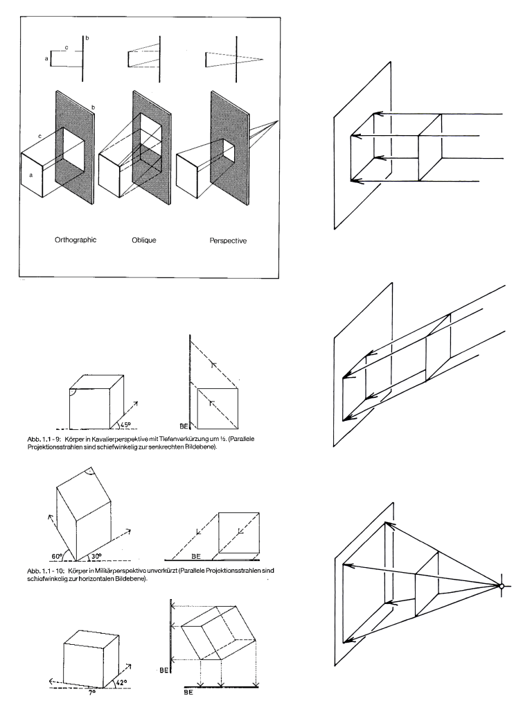
In any case, there are two kinds of projection recognised simply as: 1) shadows cast by the run’s rays which are the same size as the object when thrown onto a flat surface parallel to the object; and: 2) shadows cast by a candle, effectively a point source of light with diverging rays, giving shadows larger than the object illuminated. These two lighting systems represent the two fundamental types of projection—parallel and conical (or perspectival using a cone-of-vision). Ergo, the different systems of projection are defined according to whether the projection rays diverge converge, or run parallel to, but also are dependent on the angles at which these rays intersect the picture surface.
Drawings in all projection systems imply a certain point or direction of view from which the object is seen, nevertheless, in the parallel system the features of the object are described relative to a frame of reference based on the principal axis of the object itself, rather than being described as they appear from a particular point of view. For example, in these systems, edges are often drawn as true lengths, and edges that are parallel in the scene are represented as parallel in the picture.
In a perspective (conical projection) the objects are depicted as seen from a definite point of view. We can say that images in perspective are based primarily on transformations from viewer-centric descriptions. We can also have mixed projections (presented side by side on a single drawing page for example) which are any combination of the two different projection systems.
See diagrams below for a visual summary of the different kinds of projection lines, and the associated projection types.
Perspective Process
As mentioned, a perspective form (or geometric image form) refers to the overall (apparently transformed) geometry of a perspective image/view; including (for example) the number and position of any vanishing points, horizon lines, etc. In addition, a perspective optical image form refers to the overall (possibly transformed) light ray intensity/wavelength detected features or colour/contrast facets of a perspective image/view.
We can define optical perspective—as a subject—in the broadest and most all-encompassing terms:-
Optical perspective <IMAGING CLASS> is the formation of a 1-D/2-D/3-D visual image present in a 2-D/3-D image space, of a 1-D/2-D/3-D visual object or 1-D/2-D/3-D scene (the perspective target) present in a 2-D/3-D spatial reality. The reality in question can be a physical, mathematical, artificial, or imaginary reality; and likewise for the visual object or scene in question.
Alan Radley – 3rd May 2025

Basic Elements of Visual Perspective
It is useful to understand certain basic facts of visual perspective (2nd type or retinal form), and we now examine 3 basic concepts of how humans perceive spatial reality: the horizon line, vanishing point, and eye-level. This section of text (and the drawings in Figures 3 and 4) has been taken from the classic book: ‘Perspective Made Easy‘ by Ernest Norling (1947).
To begin let us imagine that we are standing on level land in the middle of a plain of land whereby we can see the sky meeting the distant plain in a long even line (Figure 3: top-left). This line is called the horizon line. The ideal example of the horizon is seen when viewed across a large body of water where no distant shore is seen. At sea the horizon line is one unbroken line in all directions, hence we may consider the horizon line as continuous (the horizon line is present even when obscured by objects, closed doors, viewpoint, etc).
Next, we stand between two shiny rails and look along the railway tracks (Figure 3: bottom-left). These rails go on and across the level plain until they reach the horizon where they are lost from sight (or disappear) in the distance at a point named the vanishing point. Note that the horizon line is (notionally) comprised of an infinite number (or line) of vanishing points (in image space), each vanishing point formed from a set of parallel lines (in object space) pointing in one of many different directions but all being present on the ground plane.
Now look down at your feet (projected eye-level directed downwards) , and then raise your head and look 20 feet ahead; you still see the track and vanishing point even though you are not looking directly along the tracks (Figure 3: top-right). Then look straight ahead. You see the track as it climbs to a height level with your eyes (within your visual field) and disappears in the distance. This height is called the eye-level (when you look in a direction parallel to the ground plane). The horizon and eye-level become one and the same thing (the eye-level now being projected out to infinity to match the apparent horizon line position).
Now sit down and look about, you will find that the eye-level has lowered, the distant horizon also appears lower in order to meet the change in eye-level (Figure 3: bottom-right). The horizon and eye-level become one and the same thing.

If we ascend in an airplane, we shall find that the distant horizon rises with our height, it appears to remain at eye level (Figure 4: bottom-left). This accounts for the basin-like appearance of the earth when viewed from a great height.
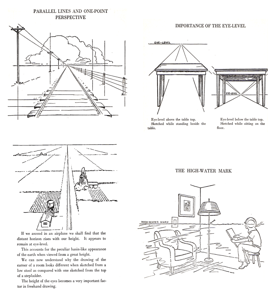
The (horizontal) eye-level is always represented by a straight line. You are seated sketching the interior of your room. Someone makes a mark around the wall the same height from the floor as your eye. This mark will appear as a straight line across your drawing, it is the eye-level. Imagine yourself wearing a diving helmet and seated in your room making a sketch of the interior. As you sit the room is filled with (imaginary) water until it just reaches the height of your eyes (Figure 4: bottom-right). Now everything that is under water is below eye level and everything not underwater is above eye level. The high water mark around the walls on everything else that it touches in the room is the eye-level itself. If you are seated outdoors the high-water mark explanation will still hold true.
The whole system of perspective drawing is based on this eye-level, as seen in Figure 4, top-right, which shows that lines/planes below eye level appear to rise to meet the eye-level, and lines/planes above the eye level appear to lower to meet it.
Note that this explanation is concerned with horizontal planes, and sets of parallels of the same; whereas vertical planes behave in a similar fashion but only with planes on the left/right side converging inwards as with the classic railway track image (Figure 4: top-left).
Vanishing Points
It is useful to break down the visual appearance transformations associated with linear perspective, a familiar type of optical perspective. In terms of an expansive spatial scene, either due to accident, or else by design, many linear perspective images are representations of a particular kind of spatial geometry; containing groups of parallel lines forming standard vanishing points as explained below.
A vanishing point is a point on the perspective image/view (e.g. drawing/painting, visual image, photograph, etc) where the 2-D projections of straight and mutually parallel lines present in 3-D object space appear to converge. Vanishing points are distant points where the outlines of objects seem to disappear (go to zero size), and most types of perspective images exhibit (or imply) vanishing points, including the linear, curvilinear, spherical types, etc.
A vanishing point is defined thusly:
Parallel lines appear to converge as they vanish (or recede from the eye), and meet at an infinite distance from the observer in an imaginary point called the vanishing point of the system (of parallel lines).
As we shall learn in the perspective phenomenon section, this definition is Axiom number one of the linear perspective method.
Vanishing Points (primary / secondary)
Why and how do vanishing points form?
To answer these questions requires a little hard thinking and geometrical analysis. Let us consider the construction of a one-point linear perspective drawing. You begin by defining a spatial reality using a ground plane containing a set of mutually parallel orthogonal lines, being co-planar straight lines aligned approximately along the central axis of observation. The formation of a linear perspective image/view happens as a result of two perspective phenomena: 1) the viewing aspect being slightly above the ground plane (sight line is above ground plane in object space); and: 2) the perspective phenomenon known as diminution of size.
Accordingly, all straight and mutually parallel orthogonal lines experience a proportional reduction in apparent or lateral ‘size’ (lateral distance from the central axis)—with increasing depth (horizontal plane). Plus the ground plane (and all sets of contained parallel lines) appears to rise towards the horizon line (vertical direction). The result is that all such mutually parallel orthogonal lines vanish into (or approach) a single central or primary vanishing point, the same being a point in image space directly opposite the viewer’s eye position.
Orthogonal Line: An orthogonal line is a parallel line in object space that is co-planar with the central axis of projection or runs parallel to the optic axis (linear perspective), and also at right angles to the picture plane.
Alan Radley – 3rd May 2025
A primary vanishing point is a point on the perspective image/view where the 2-D projections of mutually parallel orthogonal lines, present in 3-D object space, appear to converge or meet (ref. said lines notionally meet at ‘infinity’ (or never), but may appear to meet at a closer point due to image resolution limits). This same graphical construction method is one-point linear perspective.
However, one-point linear perspective (often) only depicts the converging appearance of orthogonal lines on the ground plane (and any related co-planar object plane(s)). Yet physical space potentially contains an infinite number of object plane(s) arranged in a variety of (inclined and twisted) directions, each potentially also containing groups of parallel lines, thus each angled object plane can have multiple secondary/auxiliary vanishing points.
The artist normally does not depict all these vanishing points; but simply draws a ground plane with a limited number of vanishing points (ref. one/two/three point linear perspective), and thus defines the space with sufficient realism. Yet in reality, we have countless (potential) vanishing points in every direction (multiple vanishing points for each (potential) set of parallel lines on each angled object-plane). This is what apparent optical/visual space is—an infinity of vanishing points in every direction as everything gets smaller in direct proportion as it moves away from the viewpoint.
See Figure 5 for a depiction of primary and secondary/auxiliary vanishing points in which the original object planes (and contained sets of parallel lines), are horizontal or co-planar with the ground plane, and hence all of these vanishing points fall (at some location) on the horizon line or are directed towards the notionally invisible horizon line which may be outside of the depicted field-of-view.
See Figure 6 for a depiction of primary and secondary/auxiliary vanishing points in which the original object planes (and contained sets of parallel lines), are vertical/horizontal and/or inclined/twisted, and hence all of these vanishing points fall (at some location) on a (vertical/horizontal/inclined/twisted position) horizon line or are directed towards the notionally invisible (vertical/horizontal/inclined/twisted position) horizon line which may be outside of the depicted field-of-view.
Horizontal Planes and Lines
Closely associated with the visual phenomena of the vanishing point and the horizon line, are the horizontal plane and the vanishing trace.
Horizontal parallel planes appear to approach one another as they recede from the eye, and meet at an infinite distance from the observer in an imaginary (horizontal) straight line known as the vanishing trace.
As we shall learn in the perspective phenomenon section, this definition is Axiom number two of the linear perspective method.
The (horizontal) vanishing trace of a plane must contain the vanishing points of all (horizontal) lines which lie on the plane
As we shall learn in the perspective phenomenon section, this definition is Axiom number four of the linear perspective method.
By a combination of axioms 2 and 4, we can define a horizon line as the vanishing trace of all sets, of all (horizontal) parallel lines, that lie on the ground plane (in any direction on said plane).

Horizon Line (physical/optical/true = outdoor and horizontal)
The physical, optical, or true horizon line is a visible horizon line seen outdoors and at eye-level where the physical extent of the ground plane meets the skyline in the far distance. This is a line in which vanish all lines inclined (laterally) or normal to the picture plane lying in horizontal planes (i.e. not parallel with the picture plane). It is always at the eye height and horizontal, even when the centre of vision is inclined. It is always in the picture plane.
Consider looking along railway tracks. Let us follow the railroad tracks out on the plain where there is level land in all directions as far as we can see. All around us we can see the sky meeting the distant plain in a long even line. This is called the horizon or horizon line. The ideal example is when a scene is viewed across a large body of water where no distant shore is seen – then in the middle of the sea the horizon is one continuous line in a 360-degree circle (in front of, sideways to, and behind the viewer). We may consider the horizon as continuous. This is true even when the view may be obscured by an object: a hand, building or a mountain. The (physical/optical/true) horizon is still there though we go into the building and close the door. If objects somehow became transparent the outdoor/horizontal horizon could always be seen.
The horizon line is where the horizontal plane containing the eye/camera meets the picture plane. It is the vanishing line of the ground plane and of all other horizontal planes and is the locus of the vanishing points of all horizontal lines.
Synonyms: eye-line, eye-level, artist’s eye level, skyline, physical horizon line, optical horizon line, true horizon line, outdoor horizon line, horizontal horizon line.
Alan Radley – 3rd May 2025.
Horizon Line (local vs outdoor)
In a room you create your own local horizon line, this is an eye level mark around the wall. Both this local horizon line, and the visible outdoor horizon (line), are not to be confused with the horizon line on a mechanical perspective construction. This is an artificial horizon as depicted in a geometrical or linear perspective construction, which is patently different from the outdoor visible/physical/actual horizon line.
The artificial horizon is a straight line across your drawing. The significance of the local horizon is that (for example) it defines the height of a visual plane (or sight line) that in turn determines whether horizontal sets of parallel lines or a horizontal plane appears to converge upwards towards a vanishing point or vanishing trace (when the set of lines or plane is below the sight line or visual plane) or appears to converge downwards towards a vanishing point or vanishing trace (when the set of lines or plane is above the sight line).
The horizontal line or horizon passes horizontally through the centre of vision. It is the trace on the picture plane of a horizontal plane containing the station point. The horizontal plane containing the central visual ray meets the picture plane along a straight line called the horizon. We determine the height of the artist’s eyes from the ground plane, then we draw the horizon or eye-level line along the picture plane. This is called the horizontal line. Relates to both visual perspective (2nd type) and a linear perspective construction.
Synonyms: eye/sight line, eye-level, artist’s eye level, skyline, local horizon.
Alan Radley – 3rd May 2025.
Primary / Principal Horizon Line
The primary horizon line is an apparent visual boundary line where the sky appears to meet land or water (e.g. a primary horizon line on the ground plane). It appears at the exact height of the viewer’s eyes when looking directly along the central axis. The primary horizon line can be contrasted with a secondary/auxiliary horizon line (see below). Relates to both visual perspective (2nd type) and a linear perspective construction.
More generally, a horizon line is defined by:
- The formation of a vanishing point (at notional infinity) on any object plane (located at any angle) by the apparent intersection of (uni-directional) co-planar and mutually parallel lines (on said object plane); and:
- The aggregation of an infinite number of such vanishing points into an imaginary horizon line (at a notional infinite distance) on said object-plane—each being a vanishing point formed by a different set of mutually parallel lines (each set arranged at a unique co-planar angle relative to the central axis of observation on said object-plane).
Secondary / Auxilliary Horizon Line
Secondary vanishing point(s) and associated secondary horizon line(s), being located on a plane at any angle, are contrasted from the (single) horizon line which is the apparent visual boundary line where the sky appears to meet land or water on the horizontal or ground plane. Physical space can potentially contain an infinite variety of flat planes arranged in any direction, and each has a unique horizon line; hence we can potentially have an unlimited number of secondary/auxiliary horizon lines. Relates to both visual perspective (2nd type) and a linear perspective construction.
Framework Structures
A perspective framework refers to an object space containing regular physical or geometric structures and/ or metric grids, sets of parallel and orthogonal lines, etc. Said structures, when observed/imaged, are named as regular perspective (regular shapes) as opposed to irregular perspective or irregular shaped object forms.
Useful understanding or decoding of a perspective image involves correctly interpreting image projected shape/size distortions. This is where a method such as linear perspective comes into its own; whereby (often) we employ known perspective framework structures, including known ground-plane geometry, upright picture-plane, plus parallel lines and/or a metric grid, etc.
Such structures enable humans to decode the perspective image in measurably accurate terms. Also, special types of framework structure are the basis of a linear perspective graphical construction method, enabling a geometrical construction of a valid perspective view (see below). Not every (real or physical) object space contains such framework structures, but many artistic/photographic linear perspective images reflect spaces that do contain (at least partial) framework structures.
Metric Grid
Since space is invisible, we need ways to structure spatial reality to enable reverse-engineering, or comprehension, of places/things. Geometrical assumptions—or known contexts—are used to solve such image decoding problems. We employ known perspective axes/lines/planes/grids/horizons to segment, order, index, measure, and gauge physical space. A metric grid (typically) consists of a set of real, or depicted, co-planar viewing direction orthogonal lines (perspective lines) that segment physical space, sometimes with lateral direction orthogonal lines on the same plane, thus forming a metric grid.
A metric grid is often located on the ground plane and perhaps with related co-planes/normals; then the graphical method of linear perspective may accurately reflect what is seen by the human eye, or is captured in a photograph by a camera. A perspective grid facilitates accurate image decoding/perception of a physical scene, but also enables constructed/graphical perspective images to move closer to the true geometry of spatial objects/scenes as seen in a live view (through accurate metrical segmentation and indexing of space).
In this manner, a metric grid helps to solve the correspondence problem, and by supplying a measuring grid for accurate measurement of ground plane object sizes. Related techniques such as measuring and/or height lines can also help solve such problems – at least for a regular segmented space or objects located in, or that conform to, a linear perspective projection. Certain kinds of perspective, for example, multi-view parallel perspective, can provide a complete and automatic solution to the correspondence problem. However, problems remain such as the scale/shape/size problem and the shape/form sufficiency problem (at least for the real-world spatial scene/objects that the drawings are designed to represent).
In a way, a graphical perspective method such as linear perspective is a quantitive construction of space—whereby we employ pre-determined knowledge of spatial forms—or use of known, often designed, and regular scene geometry. Not every object space contains the framework structures of linear perspective, but many artistic/photographic images reflect spaces that do contain regular perspective structure(s) of one kind or another.
The Visual Pyramid (of Sight)
Leonardo da Vinci explained perspective by postulating the existence of a ‘point in the eye’ which was the apex of his ‘pyramid-of-sight’: saying:
Perspective is nothing else than seeing a place or objects behind a pane of glass, quite transparent, on the surface of which the objects that lie behind the glass are drawn. These can be traced in pyramids to the point of the eye, and these pyramids are intersected by the glass plane… By a pyramid of lines I mean those which start from the surface and edges of bodies; and converging from a distance, meet in a single point.
Leonardo da Vinci
The pyramid-of-sight remains a fundamental concept of visual optics, that explains many features of human vision, and not least of which are the various methods and phenomena of visual perspective and related techniques of graphical perspective.
The pyramid-of-sight refers to the visual field of each eye in a stationary position. The visual field is the region of space in which objects can be seen by this eye when it is in a fixed position and does not rotate on its orbit. However, if the head is kept immobile but the eye rotates in its orbit, the visual field moves with the eye, and also the point of fixation or centre-of-vision. Consequently, the total field-of-view covered by the moving eye is considerably greater than the visual field itself.
The outer boundary of the pyramid-of-sight is defined by certain rays, the ‘main rays’, ‘chief rays’ or ‘principal rays’, which converge towards a single point in the eye from all of the different object points. Ergo, the beam profile of this pyramid of sight, when used for perspective viewing/drawing, defines the boundary or image outline of objects represented on the picture surface/plane or perspective window. Euclid named such rays the ‘visual rays’. These chief rays define the visual angles subtended by the objects, whose angles are the main subject of visual perspective. Accordingly, the study of visual angles may be called natural perspective.
Central Perspective
Central perspective (also named front or frontal perspective) is a general term for any perspective image/view in which the spatial object/scene is viewed along a single optical line-of-site producing a ‘cone-of-vision’ or ‘pyramid-of-sight’. With central perspective the entire dimensional scene is projected onto a single (often) flat picture surface or plane. Typically the perspective view/image has one or more vanishing points towards which everything is related (or converges), plus object foreshortening occurs along the optical line-of-sight. Central perspective is a form of graphical projection named central projection; a type of representation that mimics what the eye sees when looking at a spatial scene or three-dimensional (3-D) object in a frontal fashion.
In a strict mathematical sense, central perspective includes one-point, two-point, three-point projections, curvilinear perspective and (certain kinds of) parallel perspective projection. All of these projection methods are termed central perspective because in each case, the scene is viewed from a frontal direction; plus typically with scene rectilinear lines in one or more of the orthogonal, lateral and vertical directions (in object space) appearing to recede towards—one or more—fixed vanishing points (but not with parallel perspective).
Central perspective creates the impression that the represented objects behave (visually) as in physical reality under certain visual/optical conditions.

The Artistic Method
Let us begin by considering how an artist produces a perspective drawing/painting of a three-dimensional scene. Patently, the artist must first select a subject to paint (choose an object/scene), which is to be looked at from a fixed location in space, being the so-called station or viewpoint.
One might assume that the artist can begin by simply sketching what he/she sees, whilst looking at the scene in a somewhat ad-hoc manner. But normally, it is necessary to fix the viewpoint, viewing angle and field-of-view in some way; and because there are a large number of possible viewing angles and contrasting scene aspects that can be observed, each from a slightly different position, etc. The problem is that the artist’s viewing location, plus angle-of-view, can both change whilst the drawing is under construction. To solve this problem, a ‘transparent’ frame is overlaid onto the spatial scene, named the perspective window or windowpane (which may be only imaginary, and can even be wholly or partially unconscious). This perspective window is normally rectangular in shape, and planar (or flat) in form, and serves the purpose of fixing the artist’s head position (location), plus angle-of-vision and field-of-view (monocular eye position), relative to the spatial scene/object in question.
Ergo, the artist begins by looking at a scene through an imaginary perspective window (or even a real glass window or semi-transparent veil), and the drawing/painting is made as if coincident with this flat and translucent windowpane. Whereby for a representation created in such a manner, each sketched object in the scene is thus depicted as a flat, scaled-down image of the object on the other side of the window. Ergo, the technique of graphical perspective works by representing the light that passes from a scene through an imaginary rectangle (represented as the plane of the drawing/painting), to the viewer’s eyes (ostensibly a single eye).
What happens when another person looks at a painting created in this way? Well, it is as if the viewer were (him or herself) looking through the same perspective window and hence viewing a representation identical to the original scene (at least in some geometrical senses and not including binocular effects, etc). This happens because each portion of the painted object lies on the same straight line from the viewer’s eye to the equivalent portion of the real object it represents. Henceforth, the viewer sees no difference between the painted scene on the perspective window and the real-world view of the spatial scene/object (in terms of object/scene outlines).
For a painting so constructed, the picture plane can be thought of as the glass of the notional windowpane through which the viewer looks into the representation of spatial reality that lies beyond. In practice, the picture plane is the same as the physical surface of the painting produced in this manner.
When the resulting picture or representation is viewed from the same spot as the windowpane was created (or from an identical station point located the exact same distance in front of the picture), then the depicted image is identical to what was seen through the unpainted window (by the artist).
Viewer not at Station Point
It is often the case that the viewer is not located precisely at the same station point relative to the picture or photograph plane (as the original artist or photographer was relative to the original perspective window); either being at the wrong distance, or off to one side of the painting/photograph central line (at an angle relative to the plane of picture). This situation results in optical distortions being introduced into the perceived picture; and these are new ‘locally produced’ visual perspective optical distortions! Luckily, often the visual effects of such different locations are small, and human perception can account for and ignore said effects.
Ergo, in practice, unless the viewer chooses an extreme viewing angle, the perspective of a picture produced according to the rules of perspective normally looks more or less correct no matter from which location/angle it is viewed. This is referred to as “Zeeman’s Paradox”.
It has been claimed that a drawing in perspective still seems to be in correct perspective at other viewing spots because we perceive it as a drawing, and notably because it lacks other so-called ‘depth cues’. Nevertheless, the field-of-view is often narrow enough (typically approx. 60 degrees) that the distortions are minimal such that the drawing/painting can be viewed from a point other than the actual ‘artists’ station point and without appearing significantly distorted.
Indeed similar arguments help to explain why computer, television, and cinema perspective images can all be viewed from multiple and/or ‘wrong’ station-points, but without experiencing the effects of undue optical distortions. In other words, any ‘locally produced’ perspective visual distortions created while viewing flat perspective drawings/paintings/photographs etc., are generally ignored by the human visual/perceptual system.
Linear Perspective (1-2-3 Point, etc)
Renaissance, scientific, linear or one-point perspective is thought to have been devised about 1415 by Renaissance architect Filippo Brunelleschi and later was documented by architect Leon Battista Alberti in 1435 (Della Pittura). Note that linear perspective sometimes refers to one, two, three-point or even unlimited-point perspective types.
One-point perspective is a type of graphical perspective construction created on a 2-D plane that employs a central (or single) viewpoint for the depicted scene, (ostensibly) with one vanishing point in the distance which is placed on the horizon line, and from which everything in the drawing is set out (or converges). Linear perspective is sometimes taken to be identical to one-point perspective in meaning and refers to an approximate representation, generally on a flat surface, of an image as it is seen by an eye/camera (natural/visual and instrument perspective).
One-point perspective is the optical/geometrical result of projecting (from object space), a set of orthogonal parallel lines, into image space where they converge to the single central vanishing point of one-point linear perspective. As an alternative two/three-point perspective types are also (sometimes) referred to as linear perspective.
Within a spatial reality (depicted in a drawing/computer-graphic), we can have many more vanishing points or multi-point perspective, and even unlimited vanishing-point linear perspective (automatically employed in CGI – at least potentially for any spatial scene). However, all forms of linear perspective map rectilinear (straight) lines existing in the orthogonal and lateral directions within the object space to corresponding rectilinear lines in the image space (at least that is the goal). This is contrasted with curved lines in curvilinear perspective.
Unfortunately, confusion exists about how perspective arises, the circumstances in which a specific form is valid, and why it may correctly, or incorrectly, represent physical reality. Herein we shall discover the authentic sources of linear perspective, and discern its relationship to a broader set of vision/representation objectives.
First we shall take a look at parrallel perspective.
Parallel Perspective
Parallel Perspective is a form of graphical projection <IMAGING CLASS> in which the original distance of the viewer from the object/scene cannot be determined because the viewer’s position is taken to be at infinity.
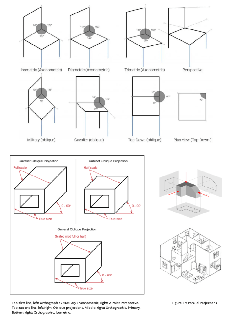
We have two types of parallel projection, being orthographic and oblique.

The Orthographic Projection (consistent object geometry)
Orthographic projection (also orthogonal projection) is a method of representing 2-D/3-D objects present in a 3-D or spatial reality in two dimensions. Within an orthographic projection, all the projection lines are orthogonal to the projection or picture plane, resulting in every plane of the scene appearing in affine transformation on the viewing surface. An affine transformation is a linear mapping that preserves points, lines, straight lines, and planes.
We have two basic kinds of orthographic projection, named primary or multi-view, and axonometric.
Primary Projection (mulit-view)
Primary or multi-view projection is a technique in which principal axes or the planes (or faces) of the object are also parallel to the picture/projection plane to create the primary views. Sub-types of primary views include plans (top-down/bottom-up view), elevations (front/side view), and sections or cutting planes through the object to allow viewing of internal structures.
Multi-view projection is so-named because the draftsman can completely define the 3-D geometry of a 3-D object by creating a drawing that shows three separate, or orthogonally related views, being plan, front-elevation and side-elevation.
Primary projection is synonymous with the drawing technique named as descriptive geometry. It may involve first-angle projection (termed first quadrant), commonly used in Britain, where one looks out at the projection: or third-angle projection, commonly used in the United States, where one looks in at the projection as if it were in a transparent glass box. Primary projections are often used in technical and engineering drawings and plans, plus in architectural drawings, etc; and because the representation has a uniform scaling that enables accurate and precise measurements to be taken directly from the drawings so constructed.
Axonometric Projection
If the principal axes of an object are not parallel with the projection plane, the depiction is called axonometric or an auxiliary view. Axonometric projection is used for creating a pictorial drawing of a 3-D object, where the object is rotated around one or more of its axes to reveal multiple sides. “axonometry” means “to measure along the axes”.
Axonometric projection is subdivided into isometric, dimetric, and trimetric projection(s). In isometric projection, all three (object) faces are equally oblique (have the same angle relative to the axis of projection). In dimetric, two faces are equally oblique. In trimetric, only one face is equally oblique.
Isometric projection is the most commonly used form of axonometric projection used in technical/engineering drawing, because the direction of viewing is such that the three axes of space appear equally foreshortened, and there is a common angle of 120° between them. Also because the distortion caused by foreshortening is uniform, the proportionality between lengths is preserved, and the axes share a common scale; hence this facilitates taking measurements directly from the drawing.
It is important to note that all forms of orthographic parallel projection create views/images that exhibit consistent geometry for the object of attention; that is the apparent object proportions are maintained across all the different views and within the limits of the projection method employed (ref. viewing aspect is the only apparent shape determinant).
Oblique Pictorial Projection (inconsistent geometry)
An oblique pictorial projection is a parallel projection in which the lines-of-sight (projection lines) are not perpendicular to the projection plane. Firstly, in an oblique pictorial drawing, the angles displayed among the axis, as well as the foreshortening factors (scales) are arbitrary. The resultant depicted geometry is partially inconsistent and alters the apparent proportions of the object (in one or more dimensions).
There are two basic types of oblique pictorial projection; cavalier and cabinet. In cavalier, the receding lines are generally drawn full length using a 30° set square. In cabinet, receding depths are drawn half-length at 45° or 60° to look more natural. Finally, in the military projection, the angles of the x and z-axis and y and z -axis are at 45°, meaning that the angle between the x-axis and the y-axis is 90°. That is, the xy-plane is not skewed, but rotated over 45°.
Oblique projection is commonly used in technical drawing. The cavalier projection was used by French military artists in the 18th century to depict fortifications. Oblique projection was used almost universally by Chinese artists from the 1st or 2nd centuries to the 18th century, especially to depict rectilinear objects such as houses, or town/city-scapes
All forms of oblique projection create views/images that are not a realistic form of perspective, and so do not correspond to any view of an object that can be obtained in practice using natural optics or visual perspective (2nd type). However, the technique yields somewhat convincing and useful results, and it is commonly used in illustrations and technical drawing.
Oblique pictorial projections are also widely used in 3-D games, museum and art gallery maps, etc., and also for public user interface terminals etc; probably because of the absence of perspective distortions which allow for wide-field and ‘aerial’ views of expansive 3-D scenes, being views that can be rapidly perceived, recognised, and understood.
In another sense, all of these different categories of parallel perspective are forms of graphical or mathematical perspective, and it is worth noting that none (ordinarily) falls under environmental, visual or instrument perspectives etc., and because they are in a sense unreal and do not occur in the natural world (cannot normally exist in the natural environment).
Naming Conventions / Ambiguities
In German literature, axonometry encompass every type of parallel projection, including not only orthographic projection (and multi-view projection), but also oblique projection.
However, outside of German literature, the term “axonometric” is sometimes used only to distinguish between orthographic views where the principal axes of an object are not orthogonal to the projection plane, and orthographic views in which the principal axes of the object are orthogonal to the projection plane. (In multiview projection these would be called auxiliary views and primary views, respectively.) Confusingly, the term “orthographic projection” is also sometimes reserved only for the primary view.
German nomenclature
- Parallel = Axonometric = (orthographic + oblique).
Non-German literature
- Parallel (A) = orthographic, Parallel (B) = oblique.
- Orthographic (A) = Primary (multi-view).
- Orthographic (B) = Axonometric (isometric, dimetric, trimetric).
- Oblique = cabinet, cavalier, military.
Confusing usage
- Orthographic = only primary projections (multi-view).
Linear Perspective Graphical Construction Method
We shall now explore how a one-point perspective graphical construction is created, by making references to the geometry and optics of a natural scene, and as sketched onto a picture plane. In other words, we use a secondary geometry to (re)produce a natural/visual perspective view. This section of text has been taken from the classic book: ‘A History of Engineering Drawing‘ by P.J. Booker (1979).
Imagine that you are standing upright and looking directly along a straight road (comprised of square-shaped stones); whereby you are looking at a type of metric grid. Ergo the two parallel road edges appear to meet at a point directly ahead, named as the central vanishing point—which appears on the distant horizon line (at the same height as the eye). See Figure 11 (bottom) and 12 (a) for the 3-D geometry of this layout. This real-world situation can be modelled or constructed geometrically, and using a generalised perspective drawing technique. Importantly this method is independent of the visual scene or happens without the need to take apparent measurements because everything is theoretically determined.

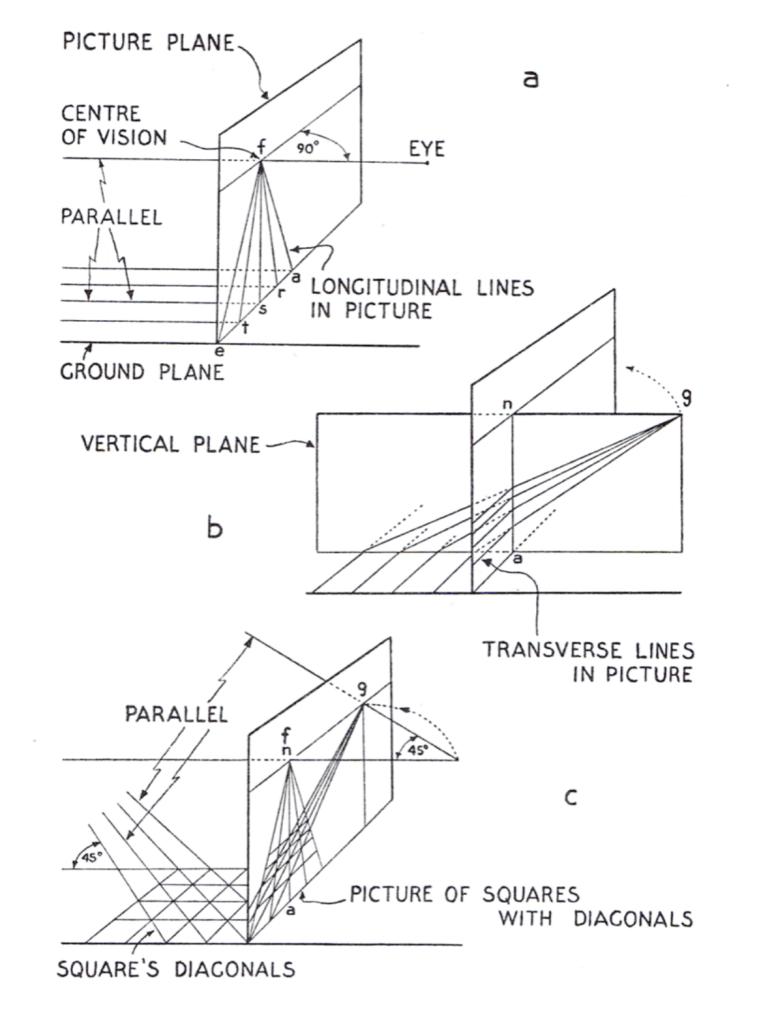
We begin as follows: If the rectangle in Figure 11 (a) is the border of the picture plane, the central point (centre of vision) could be marked as f, this point being directly opposite the eye point. At the bottom, the points e, t, s, r, a, etc, are marked off so that the divisions are equal. Next, each of the points are joined to f, which lies on the horizon of the picture plane.
To complete the picture of the metric squares (stone units), several horizontal lines are drawn. This is done on a separate sheet of paper, see Figure 11 (b), and represents a side view of the picture plane, (na), with the artist’s eye at (g). The lower horizontal line represents the ground once again, and this is marked off in equal division as was the ground line, or bottom of the picture plane in 11 (a). Each of these divisions is then connected by a series of converging lines to the eye at (g). These represent the light rays reaching the eye from the transverse divisions of the pavement and where they intersect na gives their apparent height positions in the picture plane.
Non- through Six-Point Perspective
There are six ways that a viewer can be oriented to the spatial scene, and each orientation results in a different perspective view/image. Whereby the image appearance is dependant upon the particular geometrical details and relationship between viewer, picture plane and object/scene. The following sections of text (and associated drawings in Figure 13), have been taken from the classic book: ‘The Complete Guide to Perspective Drawing‘ by Craig Attebery (2018).
Different classes of diagram are used to determine the nature of perspective image produced by a particular method of perspective, as explained below and depicted in Figure 13.
None or Zero-Point Perspective
We have two different meanings for the term non-perspective or zero-point perspective. Firstly, any image of for example a natural landscape without any parallel lines is named zero-point perspective and because no parallel lines exist in the object space form which any linear recession or vanishing points can form. Secondly, non-perspective also can be applied to various kinds of parallel projection in which perspectival recession, or diminution of size, does not occur. The latter images still have aspect foreshortening of the first projection angle type, but does not show perspectival foreshortening.
One Point Perspective
In 1436, Leon Battista Alberti published the first example of a one-point perspective image construction, in his book ’On Painting’. In one-point perspective, the vertical and horizontal dimensions are parallel to the picture plane, and vertical orthogonal lines are drawn perpendicular to the horizon line, whilst horizontal orthogonal lines are drawn parallel to the horizon line. Depth is foreshortened according to the rules of linear perspective indicated earlier.
Two Point Perspective
Drawing an object in two-point perspective first appeared in the early part of the 16th century, and in two-point perspective, horizontal lines are angled relative to the picture plane, and thus perspectively foreshortened. The lines connect to a left vanishing point, or a right vanishing point. Only vertical lines parallel to the picture plate are drawn as true vertical lines.
Three Point Perspective
A rudimentary explanation of three-point perspective appears in the Codex Huygens, a sixteenth-century work that may be the work of Leonardo da Vinci. Three-point perspective demonstrates the effects of (for example) looking up: a type of worm’s eye view. In this form of perspective, no lines are parallel to the picture plane, the centre of vision lies above the horizon line. There are left, right and vertical vanishing points.
Four Point Perspective (Cylindrical Perspective)
Prior to the time when the cone of vision was fully understood, some artists attempted wide-angled views – but with odd results because they could not compensate for the distortions introduced by using a flat picture plane. Four-point perspective is a type of panoramic view, because it displays information that remains unseen in ordinary circumstances.
It has four vanishing points, each being 90-degrees apart. In the horizontal plane, the picture plane is curved and surrounds the viewer like a cylinder, producing a 360-degree image view. In the vertical plane, the picture plane is flat, and to prevent distortion the vertical image area remains or less than 60-degrees. Also, vertical orthogonal lines are drawn vertically straight. Horizontal orthogonal lines do not appear parallel on the picture plane, and are drawn curved. We can also turn the entire drawing by 90-degrees to form a panoramic view of the vertical dimension.
Five Point Perspective (Curvilinear Perspective)
Five-point perspective, sometimes called fish-eye or curvilinear perspective can be traced to Jan van Eyck’s painting ‘’The Arnolfini Portait’, from the year 1434. In five-point perspective, the picture plane is a hemisphere, creating a 180-degree image where everything is depicted from east to west and from north to south. There is a vanishing point at the top of the hemisphere and one at the bottom, plus one on the left and right, The fifth vanishing point is the centre of vision. Five-point perspective is a multi-directional view/image of a scene as projected from multiple angles simultaneously.
Six Point Perspective (Spherical Perspective – Sphere of Vision)
A six-point perspective displays everything in front of the viewer, and also everything behind the viewer – producing a full 360-degree image! The picture plane is a sphere, and two show both sides of the hemisphere at once the images are often placed adjacent one next to the other. Six-point perspective is a multi-directional view/image of a scene as projected from multiple angles simultaneously. Relates to sphere-of-vision perspective as explained below.
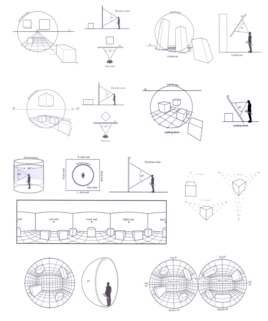
Second Row Left: Two-Point, Second Row Right: Three-Point Third Row Left: Four-Point (Cylindrical Perspective),
Third Row Right: One/Two/Three-Point Projection of a Cube.
Bottom Row Left: Five-Point (Fish-eye or Curvilinear Perspective), Second Row Right: Six-Point (Spherical Perspective)
Curvilinear Perspective
It has long been known that perspective images/views produced by the methods of linear perspective are not the only, or even definitely the most natural or realistic way, to produce views/images of a spatial reality. In particular, at the outer extremes of the human visual field, parallel lines become curved, as in a photo taken through a fish-eye lens.
It may surprise you to learn that the human visual field has a natural curvilinear shape! However, painters, building designers and scientists have been aware of this fact for hundreds and possibly even thousands of years. It has been claimed, for example, that the Ancient Greeks made the Parthenon columns bow outwards to account for—and correct—the curvilinear shape of the human visual field. Also, painters like Leonardo Da Vinci and Turner added curvilinear effects into their depictions to more closely mimic physical reality as seen by the human eye.
It is possible to graphically re-create scenes in which the geometry conforms to an overall curvilinear shape similar in form to the views projected by a fish-eye lens. This form of perspective has been called curvilinear perspective, and it is a form of perspective which has an undeniable origin in the natural optics of scenes.
At this point, you may be asking yourself why it is that photographic, film and also television images do not exhibit scene curvatures. The answer is that they would if they covered a wide enough field of view—say around 180 degrees, and in any case optical designers have worked hard to ensure that the camera lenses involved eliminate such “distortions”. Note that “Fish-Eye” wide-field lenses do show image curvatures and such views are not curved because of any effect introduced by the lens itself, but rather because that is how physical reality looks when you decide to project a scene over a very wide field of view (onto a flat picture plane)! Eagles and birds see the world like this, that is in the ultra-wide field aspect. This fact leads us to conclude that curvilinear perspective has a strong foundation in reality.
Spherical Perspective
The various types of Spherical Perspective have long been a subject of fascination in the graphical arts, plus in optics and human vision.
In the nineteenth century, Hauck (1879), believed that the subjective curvatures of Greek architecture corresponded to spherical theories of vision. In the nineteenth century, Helmholtz (1866, 1896), developed a new demonstration involving a curved checkerboard to illustrate subjective curvatures. Two important examples evolved: one using the vault of the heavens, e.g. Reimann (1890-1891) and Zoth (1899), the other using the apparent bending of light from lighthouses on the horizon, e.g. Bernstein (1904).
The 20th century has seen an increasing interest in relating spherical projections of optical theories with painting practice. Deininger (1914) claimed that:
Only (on such) a spherical surface is it possible to represent graphically all those lengths i.e., all the perspectival dimensions in their correct relations and proper sizes.
An important book by Jobin (1932), argued that with the development of skyscrapers one needed to apply perspective to the vertical as well as the horizontal axis. Later Spherical Perspective was taken up afresh by Barre and Flocon (1962, 1964, 1968). During the 1970’s problems of Spherical Perspective inspired the imagination of American artists. Hansen (1973), developed a five-point spherical perspective, which he termed Hyperbolic Linear Perspective. Independently, Termes developed 4, 5 and 6-point Spherical Perspective methods.
Here is an explanation of the Sphere-of-Vision by artist, Dick Termes (personal communication to Kim Veltman):
If you think of yourself inside a clear ball and you are looking out at a total cubical room outside the sphere and you copy what you see through the sphere onto the inside of the sphere. Now you have the whole cubical room scene painted on the sphere just like you see it. Looking at the cube room you will find three sets of parallel lines that make up the room. In Spherical Perspective all parallel lines don’t just go to one vanishing point they go to two. If they aim to the north vanishing point they will also be aiming and vanishing to the south vanishing point. Another set of lines go to the east and west point and another go to the up and down points. These six vanishing points are the same points as the vertices of the octahedron. The octahedron has eight faces to it. The three point perspective uses three of those points. Those three points are enclosing one of the eight triangles of the octahedron. That is where I get that it is one eighth of the total picture.
Dick Termes
Spherical Perspective methods have been made analogous with curvature of the retina, and many experts have made a distinction between objective retinal space (curved) and subjective visual space (possibly Euclidean). Hegenwald (1931) claimed that one needed to choose a particular viewpoint for which collinearity, and consequently Linear Perspective was best suited. He concluded that Linear Perspective remained the most rational method developed thus far. Alternatively, in France, an important study by Nicod (1962), brought an introduction by Bertrand Russell, which claimed to prove that visual space is spherical. Overall, during the last 50-60 years, artists and scientists have taken an increasing interest in the methods and applications of Spherical Perspective.

Spherical Perspective: Types / Forms
Spherical Perspective can be split into six kinds/forms:
- Sphere-of-Vision (image/view of total Visual-Sphere)
- Sphere-of-Revolution (Multi-View Perspective)
- Spherical Display (internal/external types)
- Glass Sphere (Transparent spatial view/image)
- Metal/Mirror Ball (Reflected spatial view/image)
Let us take each in turn.
- Sphere-of-Vision: uses an eye/camera/representation to produce a super-wide-angle perspective image of an actual, virtual, or approximate/partial 360-degree spatial scene; which is similar to Dick Termes method of artistic representation.
- Sphere-of-Revolution: (a form of Looking-In/At Perspective) uses an eye/camera/representation to explore close-up/narrow-field images of a spatial object/area; whereby these same views are obtained by revolving in a sphere surrounding the object in question to gather images from many/all positions on a 360-degree sphere.
- Spherical Display (A): a dome-shaped sphere which surrounds or immerses the viewer into a total spherical image space (ref. IMAX/Sphere Theatre).
- Spherical Display (B): the outside of the sphere becomes the display surface for a 6 primary vanishing point perspective (6 PVPP).
- Spherical Display (C): relates to the ‘living’ optics of a natural scene; and we can have either a transparent glass-ball through which a spatial scene is viewed in 5 primary vanishing point perspective (5 PVPP); and also a reflective metal-ball which creates a partial visual-sphere.
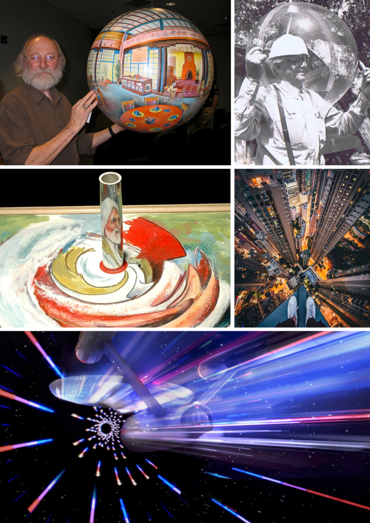
Middle Left: Anamorphic Cylinder Perspective Illusion. Middle Right: Vertical Vanishing Point Perspective.
Bottom: Star Trek CGI Perspective (new media perspective).
Anamorphic Perspective
We have noted that perspective works in two directions: to record an image backwards onto a picture plane <IMAGING CLASS> and to project it forwards <PROJECTING CLASS>. In either case, as long as the object and picture/image are in the same plane, the image remains undistorted (or isometric), and varies in size only. When the object and picture plane are not parallel, the perspectival image changes shape. In the case of perspective images recorded onto the picture plane these changes are usually unwanted/inconvenient and are referred to as perspectival foreshortening or, in extreme cases, as perspectival distortions. By contrast, anamorphosis involves deliberate changes in shape produced in the case of images projected forward onto a projection plane.
The principle of anamorphosis is identical to that of projecting the Tropic of Capricorn in the Astrolabe, the sphere in various cartographic projections and of shadow projections in Sundials. That those interested in anamorphosis were often also concerned with projections in astronomy, cartography and sundials is no coincidence because it reminds us that the development of perspective was more than an artistic phenomenon: it was intimately connected with the rise of the mathematical sciences in the Renaissance.
Although there exist a nearly infinite number of possible projections from a plane of one shape onto a plane of another shape, early sixteenth and seventeenth-century practitioners concentrated on a surprisingly small number of alternatives: a flat projection plane at right angles to the original, a flat projection plane at right angles to an original cylindrical, conic or pyramidal plane. In the cases of cylinders, cones and pyramids a mirror was positioned in the plane of the original object such that the anamorphic forms could be transformed back to their original shape. Anamorphosis thus demonstrates the principles of transformation and reversibility basic to linear perspective.
The nineteenth century drew attention to anamorphic optical illusions. The twentieth century has continued to be fascinated by these. A number of M.C. Escher’s works are deliberate juxtapositions of sections in linear perspective which, when combined, result in impossible spaces. This is an example of explorations of non-correspondence between object and representation. In the 1950s anamorphic film formats were used to expand the cinematic field-of-vision, and these are still used today in movie making, as so-called ‘scope’ camera lenses and related projection systems, or wide-screen television formats.
Conclusion
We have now completed our brief tour of classic forms of graphical perspective; namely central, parallel, cylindrical and spherical perspective(s), whereby central perspective encompasses linear and curvilinear perspective(s). However, our discussion has not been limited to graphical perspective, because this form of technical perspective has a close connection to processes ongoing in the natural, visual, mathematical, and instrument perspective categories, etc., and so we have included a detailed exposition on those.
Hopefully, the reader has gained a clear impression of what a perspective form actually is, in and of itself. A perspective form (or geometrical image form) is the visual image shape outcome(s) of a perspective process [visual contents of image], and refers to the overall (apparently transformed) geometry of a perspective image; including (for example) the object/scene outline structure(s), number and position of any vanishing points, horizon lines, etc. Where a perspective process consists of one or more perspective categories, such as visual, mathematical, graphical, instrument, simulated, and new media perspective types.
However, matters are not always so simple. As per our concept of combined category/form ambiguity, sometimes a perspective type (or term) appears to be both a perspective category and perspective form (geometrical image form) simultaneously. But why is this so? The answer is that linear perspective is a name that applies to both a perspective category (a method/process) and a perspective geometrical image form simultaneously. This happens because optical perspective is defined as an image-making procedure, and it becomes clear that we can refer either to the process and/or outcome(s) as required (and further that these may be inextricably linked or related in optical/geometrical terms – and so named under the same moniker).
I know this double-meaning explanation appears complex and/or contrived, but don’t shoot the messenger, so to speak. The inherent ambiguity between the concepts of perspective category and form is a major cause of confusion for ‘perspective’ students of today and in the past. Certainly, it was for me as a student at school, college, university, and beyond!
One example of the improved clarity offered by this scheme, is that we can have an identical linear perspective image form as the outcome of more than one perspective category or process (ref. an image with a central vanishing point for sets of orthogonal parallel lines). Ergo, graphical and photographic perspective can both create an identical image form (for the same spatial scene/object). Thus linear perspective refers to a graphical construction method, but also to the outcomes of any perspective category that has similar framework structures in object space (e.g. sets of orthogonal lines), plus can project a view/image of said space in a similar ‘linear’ fashion as with the linear perspective method. Where both the linear perspective graphical construction method, and the various category types, produce the same geometrical image form (e.g. perspective image with central vanishing point).
In summary, our perspective category theory clarifies the multiple and sometimes confusing usage of perspective terms. This is evident with linear perspective which has many variants/doppelgangers; firstly with different (process) categories including the graphical, photographic categories, etc., and secondly different (transformed) geometric image forms, or apparent object/scene outline structures, such as one-point, two-point, three-point perspective images, etc.
-- < ACKNOWLEDGMENTS > --

AUTHORS (PAGE / SECTION)

Alan Stuart Radley, April 2020 - 16th May 2025.

Kim Henry Veltman, partial sections on Curvilinear and Spherical Perspective, plus the Anamorphic Perspective section have been extracted from: 'The Sources and Literature of Perspective', 2004.

Ernest Norling, partial section on the Basic Elements of Perspective have been extracted from:  ‘Perspective Made Easy‘, 1947.
---

TEXT / IMAGE EXTRACTS

Ernest Norling from: ‘Perspective Made Easy‘, 1947.
P. J. Booker from: 'A History of Engineering Drawing', 1979.
Craig Attebery from 'The Complete Guide to Perspective Drawing', 2018.
--

BIBLIOGRAPHY

Radley, A.S. (2023-2025) 'Perspective Category Theory'. Published on the Perspective Research Centre (PRC) website 2020 - 2025.

Radley, A.S. (2025) Perspective Monograph: 'The Art and Science of Optical Perspective', series of book(s) in preparation.

Radley, A.S. (2020-2025) the 'Dictionary of Perspective', book in preparation. The dictionary began as a card index system of perspective related definitions in the 1980s; before being transferred to a dBASE-3 database system on an IBM PC (1990s). Later the dictionary was made available on the web on the SUMS system (2002-2020). The current edition of the dictionary is a complete re-write of earlier editions, and is not sourced from the earlier (and now lost) editions.

Veltman, K.H. (1994) 'The Sources of Perspective' - published as an online book (no images). Later published with images as 'The Encyclopaedia of Perspective' - Volumes 1, 2 - (2020) by Alan Stuart Radley at the Perspective Research Centre.

Veltman, K.H. (1994) 'The Literature of Perspective' - published as an online book (no images). Later published with images as 'The Encyclopaedia of Perspective' - Volumes 3, 4 - (2020) by Alan Stuart Radley at the Perspective Research Centre.

Veltman, K.H. (1980s-2020) 'The Bibliography of Perspective' - began as a card index system in the 1980s; before being transferred to a dBASE-3 database system on an IBM PC (1990s). Later the bibliography was made available on the web on the SUMS system (2002-2020). In 2020 the Bibliography of Perspective was published as part of'The Encyclopaedia of Perspective' - Volumes 6, 7, 8 - by Alan Stuart Radley at the Perspective Research Centre.
---

Copyright © 2020-25 Alan Stuart Radley.
All rights are reserved.

You must be logged in to post a comment.